We recently acquired a Freematics On Board Diagnostics (OBD) II dongle and played around … ehrm sorry tested it thoroughly over the course of the last two weeks. Since there was a steep learning curve we are giving this articel in a tutorial style to spare others some of the pain we encountered during this time. The tutorial is targeted at anyone who already knows some programming.
If your are living in the EU however be careful! It was a painful experience for us to learn that, since the Freematics OBD II dongle is not CE certified, it is illegal to import and use in the EU area. If customs finds your shipment, they are going to destroy it without further notice and you will not receive a notification that this has happened.
The dongle is one in our growing zoo of data capturing devices. It may be plugged in the OBD II port of any car, which every car manufactured after january 1st 2004 has. The dongle contains the basic sensors necessary for capturing street quality information as well as transmission technology to push the data to our data cloud. The unpacked product is depicted in Figure 1.

Figure 1: Freematics OBD II Dongle – Box Content
The great thing about this technology is its openness. The stick itself is open hardware, while the software is available via GitHub. It is based on Arduino technologie and programmed like an Arduino Uno with already installed:
- OBD II Connection: For power and vehicle diagnostics data
- MPU 6050 – 6 axis inertia measurement unit (IMU): For capturing acceleration and rotation data
- GPS Module: For capturing location data. This is also extensible with an external antenna, which, according to our previous experiments is absolutely neccessary.
- xBee Module with ESP8266 (WiFi Connector): For transmitting data via WiFi. You can get this with an UMTS module as well, but for testing purposes we decided to order the WiFi variant. You can of course just order the appropriate xBee module and switch it for the one you require.
- SD Card Slot: For Storing data as long as no WiFi is available (similar to how our Android App works)
- Bluetooth: We do not need this but it is a great option to pair the dongle with a smartphone and provide live feedback while driving or something similar.
Since we are software guys, it is great to have such a niffty piece of hardware. Unfortunately the software coming with the stick is not as perfect as we would like it to be. However since it is open source and even though it has been some time since I saw the last C/C++ code, we decided to put some effort into it. In order to use the stick for our services we need to extent the existing code base with the following feature:
- Enable data transmission not only to the cloud server provided by freematics but to a custom server of our choice.
Arduino: The Basics
This is no exhausting Arduino tutorial, but since the Freematics OBD II dongle is an Arduino Uno at its core it is necessary to know at least some basics. Many of the necessary steps are already described on the Freematics page. I strongly suggest to read that article. It describes most of the basics you are going to need. The following paragraphs contain some additional stories from the field.
If you come from standard software development, like we do from the Java world, everything is a little bit strange in embedded Arduino development. Programs suddenly are called sketches and even though there is an Integrated Development Environment (IDE) its features are not on the level you are probably used to. There are no line numbers, no auto-completion and no clicking on method calls to get to the definition, to name just a few things. Nevertheless I strongly suggest using the provided IDE. I spent half a day searching for an alternative and even though there are some available, none of them worked for me. If you are on Windows, and not Ubuntu like me, you might have better luck using one of the alternatives for example described on the following site. Most promising is the extended Eclipse version called Sloeber or the Visual Studio Plugin.
There are several things necessary to know to successfully deploy or develop an Arduino sketch. The main code block is stored in an *.ino file. The programming language used is C/C++. If you know Java or JavaScript and how to search StackOverflow, you should be able to make small working adaptations to existing sketches. Both languages are based on the syntax of C/C++ and thus many things should look familar. Every line starting with a ‚#‘ is a preprocessor directive. The preprocessor is a program that builds one big code file for the compiler to consume. It removes code after false #if directives, includes files after #include directives and replaces every symbol defined by a #define directive with the actual value. If you see a variable preceeded by a ‚*‘, that is one of the infamous pointers. They are variables storing a memory address. If you want to use them you need to dereference them using ‚*‘ and you can assign the address of another variable using the ‚&‘ operator. You should read some C/C++ documentation if you want to fully understand that. If not, just be careful around them and mostly leave them alone. It is possible that there are additional header files ending on *.h storing declarations. These files are for example necessary because in a C/C++ file a certain section of code only knows about symbols defined before that section. So if you got a circular dependency of code lines you need a header file to declare all symbols prior to their first usage.
If you want to upload a sketch to your FreematicsONE, which is an Arduino Uno at its core, you need to choose the correct Arduino Board, a programmer and the serial interface to use to upload the binaries. For the FreematicsONE the correct board is the Arduino Uno ;). As your programmer you choose USBasp and an appropriate serial port! The serial port is most likely the USB port your FreematicsONE is connected to. Under Ubuntu Linux it is called something like ‚/dev/ttyACM0‘. On Windows it is probably called something else. If the IDE does not give you a port to select and you are sure your FreematicsONE is connected, check your cable first. It took me one day until I found out that the cable that came with my FreematicsONE was defect and the second cable I tried was so as well ;). Figure 2, Figure 3 and Figure 4 show how to choose the correct setings.
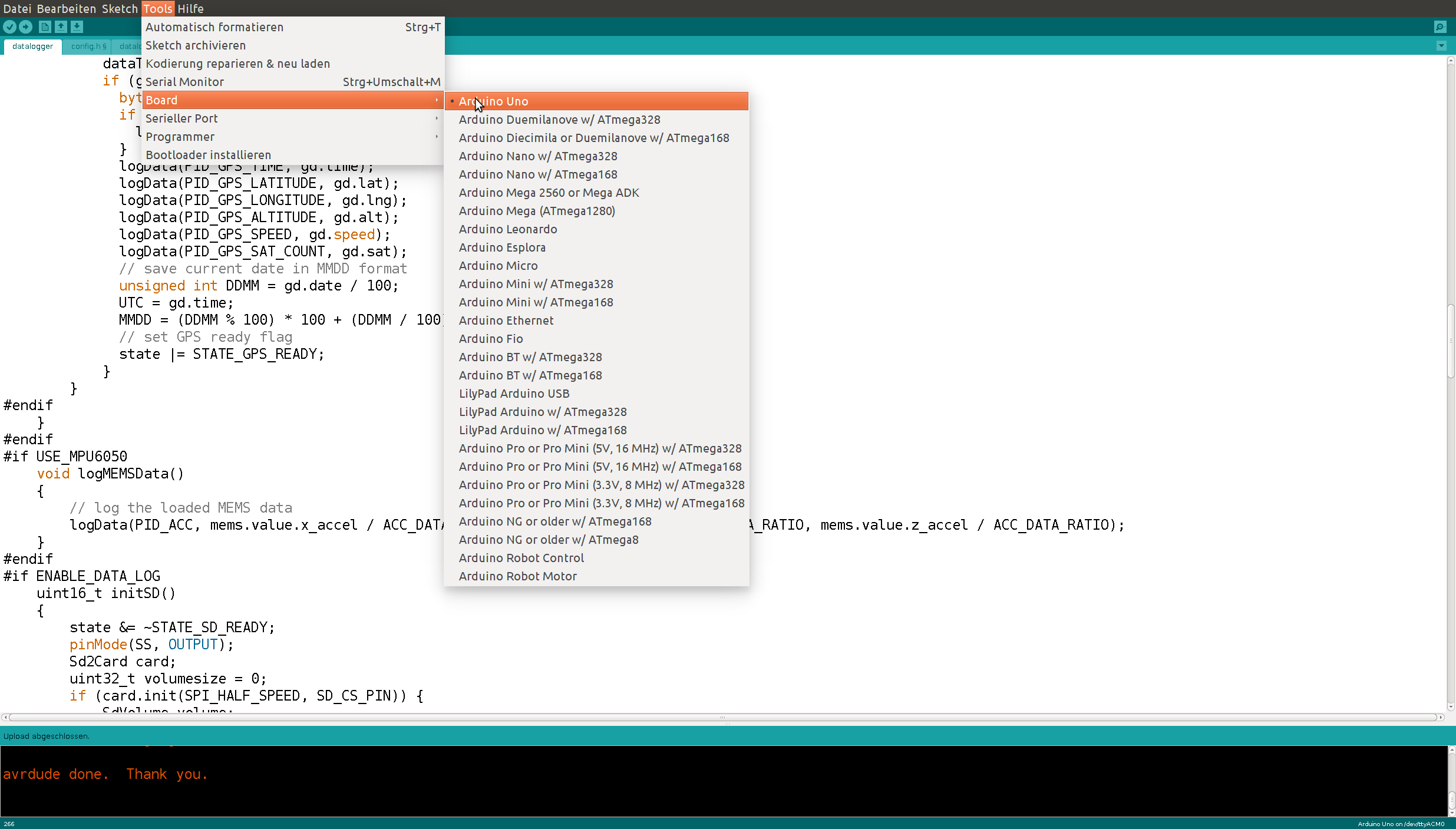
Figure 2: Choosing the correct Arduino Board Type
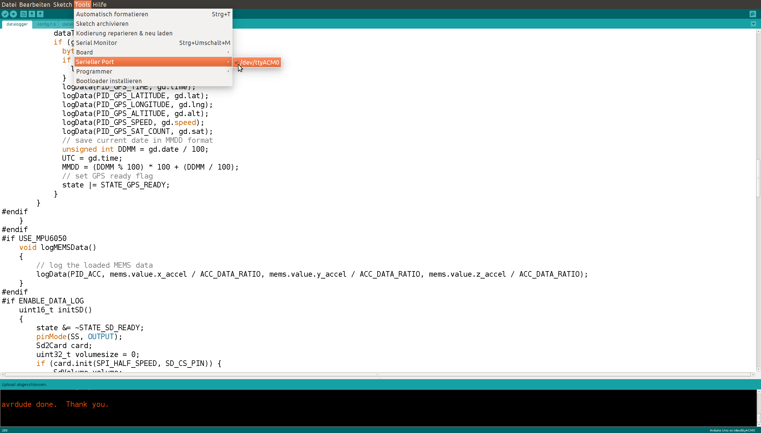
Figure 3: Choosing the correct serial port
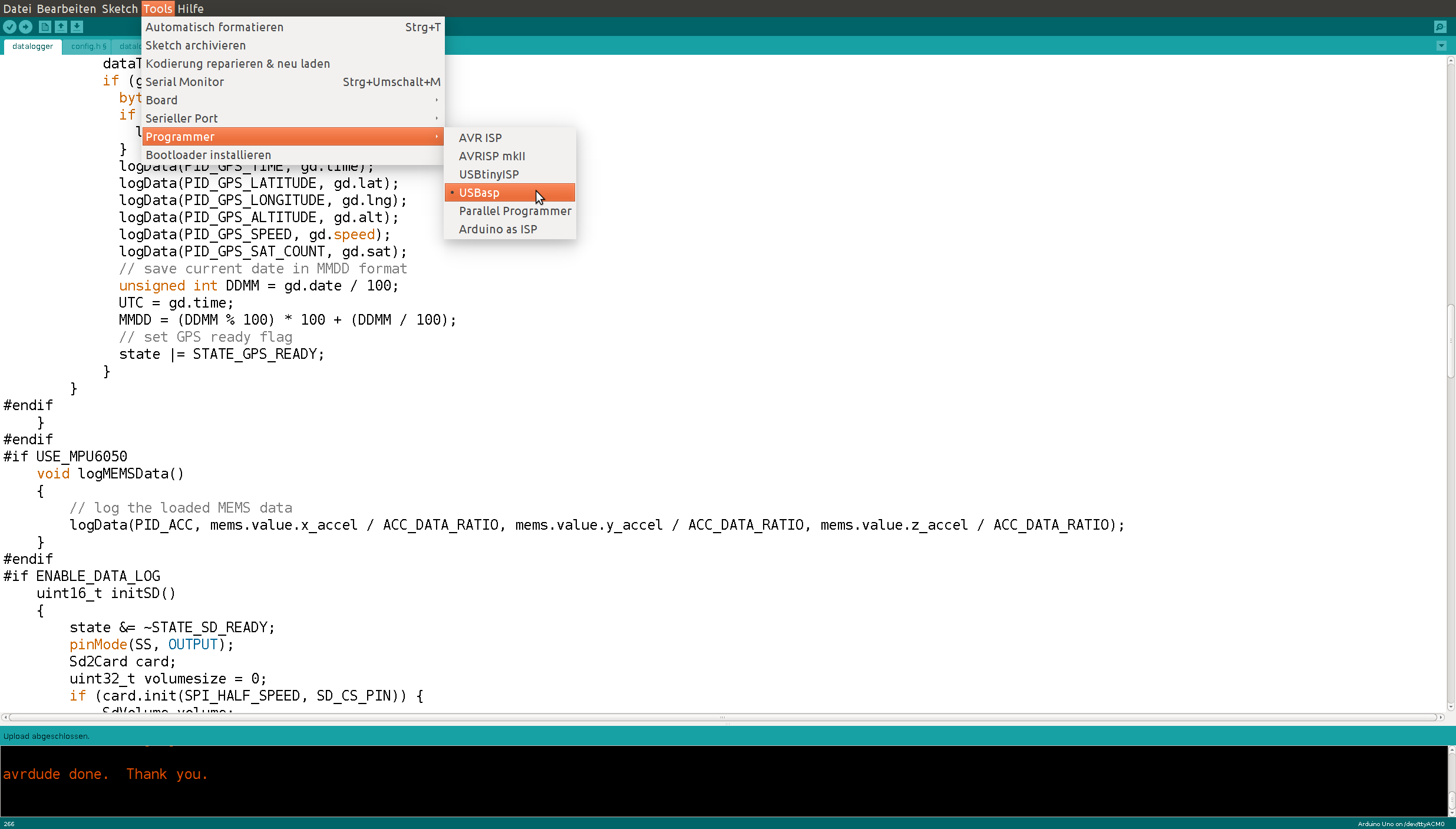
Figure 4: Choosing the correct programmer
The buttons in the upper left corner are for ‚compilation‘ ![]() of your sketch and for ‚compilation and upload‘
of your sketch and for ‚compilation and upload‘ ![]() . Upon ‚upload‘ the Arduino is going to directly start executing what you provided it. You can monitor the progress via the output the Arduino broadcasts over the serial port. The problem is that you need to start the serial monitor manually and you can only start it after you uploaded a sketch. So you need to be fast not to miss anything. The hotkey is ‚Ctrl+Shift+M‘. Hit all three keys as soon as the black terminal at the bottom of your IDE tells you ‚avrdude done. Thank you.‘. The appearing window looks like Figure 5.
. Upon ‚upload‘ the Arduino is going to directly start executing what you provided it. You can monitor the progress via the output the Arduino broadcasts over the serial port. The problem is that you need to start the serial monitor manually and you can only start it after you uploaded a sketch. So you need to be fast not to miss anything. The hotkey is ‚Ctrl+Shift+M‘. Hit all three keys as soon as the black terminal at the bottom of your IDE tells you ‚avrdude done. Thank you.‘. The appearing window looks like Figure 5.
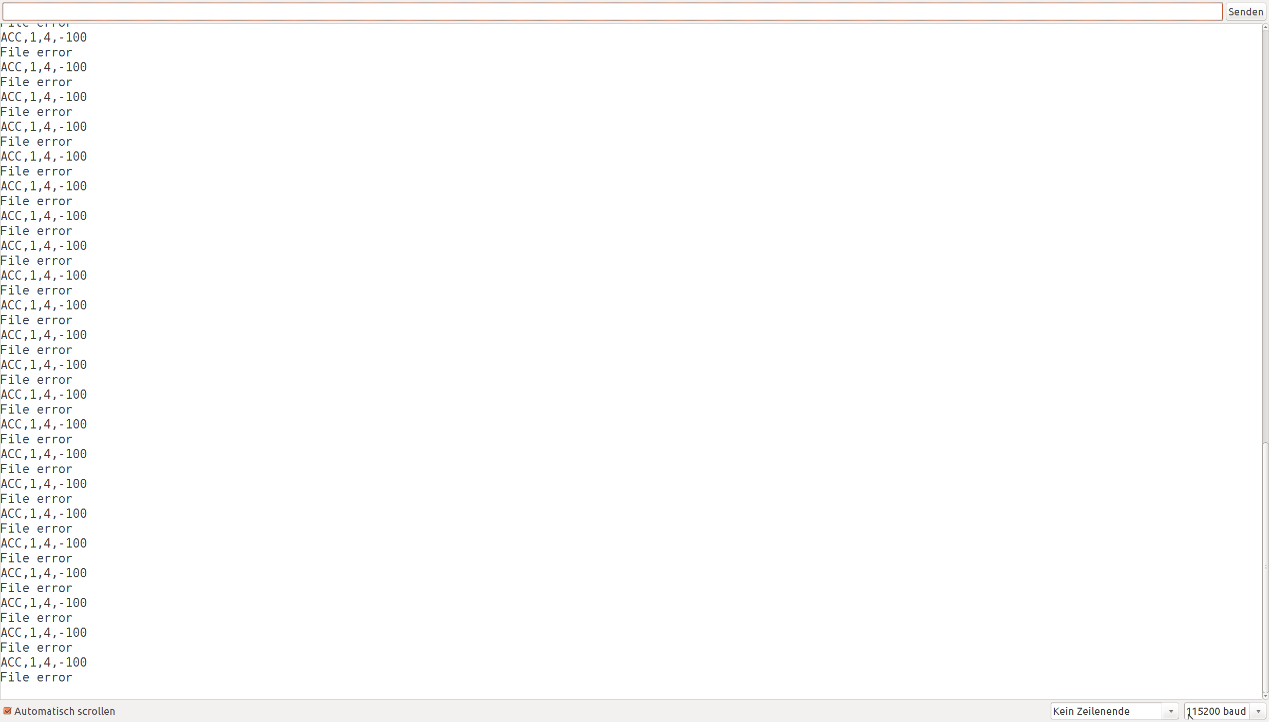
Figure 5: Arduino Serial Output Window
Notice the setting in the lower right corner? It took me some time to find out, but you need to set it to the correct baud rate or else you will only see gibberish. The baudrate is set somewhere in the program via the line Serial.begin(115200);. You need to match both numbers to be able to read the output. You can only open this window if you upload a sketch to the Arduino from your computer. So even though the Arduino starts the last uploaded sketch every time you connect it to a power source, you actually need to reupload your sketch to see what is happening. This is especially hard for diagnosing unexpected errors.
From time to time you are going to encounter an error like ‚avrdude: stk500_recv(): programmer is not responding‚ and the upload process will either finish with an error or run indefinitely. Disconnecting and reconnecting the FreematicsONE helps to fix this problem. Wait a few seconds after disconnecting it, plug it back in and upload the sketch again. If it ran indefinitely you probably need to shut down the upload process manually via your task manager (or htop under Ubuntu Linux) or it will keep running in the background eating up a huge amount of your systems resources.
The Freematics Software
After you successfully started up your Arduino IDE you need to get the sketches and the libraries for the Freematics OBD II Dongle. Be careful! There are several locations and you need to make sure to take the library from the same as the sketch code. This cost me some time to figure out, so make sure you choose the correct association. For most software you should take the stable version, but in the case of the Freematics sketches I recommend using the Nightly builds. Especially if you are going to extend them. The best way to go in that case is to fork the project on GitHub and develop on your own repository. Since the nightly build did have some problems we created our own Cyface fork, which I recommend to download until our fixes have been integrated into the core Freematics library. Table 1 list all available sources for the Freematics library and sketches for your convenience.
Table 1: Locations for the Freematics library and sketches.
| FreematicsONE Library | Sketches | |
|---|---|---|
| Stable Version on SourceForge | link | link |
| Nightly builds on GitHub | link | link |
| Cyface fixed version of Nightly | link | link |
The available sketches are described on the Freematics page. The most important ones are the datalogger and the telelogger. The datalogger is the software preinstalled when you get the FreematicsONE, while the telelogger can be used to upload data to the cloud. It forms the basis for the adaptations we are making for cyface, but what we really need is a merged version, capable of storing data to the SD card and uploading it as soon as Wifi is available.
Unfortunately there is no server implementation for the telelogger. So if you do not want to upload your data to the Freematics cloud you are pretty much stuck with developing your own solution. Luckily we already did this. The following section describe the Freematics client software on the FreematicsONE OBD II dongle and some details we found over the course of the last weeks. Afterwards we present our own cloud server implementation, which is available as open source from GitHub.
There are two most important things you need to understand to extend or adapt the FreematicsONE client code.
Firstly most hardware functions are encapsulated in the class COBDSPI from the FreematicsONE library. You should use that class extensively. Unfortunately the documentation is not perfect, so you probably need to try out many things and print results to the serial monitor to understand the things that are happening. The best documentation is attached to the library code as comments and you can find it here. Nevertheless I tend to implement small example sketches to find out the details.
Secondly the ESP8266 Wifi module is programmed using so called AT commands. You need to send them as strings to establish a TCP or UDP connection and even though they look a bit cryptic they are actually easy to implement. Each AT command returns a one byte result. You can find the meaning of that number for example here. In most cases if you receive a 0 everything is fine. Try it by just sending „AT“ to your WiFi module and check for a 0 result! A very good tutorial for the AT commands used with the ESP8266 (unfortunately only in German) is available here. Freematics also provides an example sketch.
The Cyface-Freematics Server
Our goal was to implement our own cloud server capable of communicating with the Freematics telelogger. Since we are hardcore Java developers we use Java with SpringBoot for the implementation. It is available under MIT license via GitHub. The advantages are that at least on server side most of the low level network communication is handled by the framework. However there have been several hurdles on the way to receive Freematics data on our server.
The first one was that Freematics uses HTTP for transmission. They probably implemented both sides – server and client – themselves and so got no issues, but the HTTP standard is quite complex and the implementation in the telelogger unfortunately is not correct. Since SpringBoot starts up an embedded Tomcat server, which most surely has a complete and correct implementation of the HTTP standard communication of the FreematicsONE with the server was not possible at first. We needed to add the mandatory Host header to establish communication. Additionally the Freematics client does not handle the HTTP Connection: keep-alive header correctly at the moment. Instead of parsing the servers timeout time and reestablish a connection after that time has passed it just reconnects after a certain error count. That causes a certain overhead and results in lost data during reconnections.
Secondly the Freematics data format is fairly optimized but also hard to understand. A server processing that format needs to parse the data correctly. It took some time – and might not even be finished – to interpret all those entries correctly, even though there is a description available on the Freematics page. The most important thing you need to understand is the timestamp format. Each entry is separated by a space and starts with a timestamp. Considering the first few lines from the example dataset from the Freematics page:
#5506,10D,55
 0,ACC,-913,18,528
 0,GYR,-9,-22,17
 111,104,0
 0,ACC,-922,6,548
 0,GYR,1,-27,17
It captured some information from OBD II with id 10D at 5506 seconds after the sketch started running. At the same time (5506 seconds after start) it captured an accelerometer and a gyroscope value. At 111 ms later, which means 5506 seconds and 111 milliseconds, it captured some information from OBD II with id 104. At the same time it captured another accelerometer and gyroscope entry. One thing that is still unclear is the unit used for accelerometer and gyroscope values. It should probably be divided by some constant. Unfortunately the documentation contains no information about this, so we will have to do some experiments in the near future.
Open Issues
As already mentioned in the previous sections we still have three big open issues with our server implementation, which we intend to fix in the course of the next few weeks.
- Provide a correct handling for the HTTP keep alive header to reduce the amount of necessary reconnections. An alternative would be to transfer all the data directly via TCP, but this would also remove most of the convenience provided by SpringBoot on the server side.
- Refactor the servers data parser. It currently parses something, but does this on our initial assumptions about the Freematics data format which are wrong, as we recently found out. So while the server is usable as a proof of concept its output is not usable at all at the moment.
- Merge the datalogger and the telelogger into a cyfacelogger capable of storing all data to SD card and transferring the cached data to the Cyface cloud if Wifi is available.